This page was last updated on Sept 1 ,2011
The vat (resin holder) and stage(the building platform) is such a controversial subject that I gave it its own category.Discussions are always going deep into all kinds hydrophilic and hydrophobic materials and methods , Good ideas and bad ideas. This connection plane or first adhesion layer ,so to speak, is also the heart of the whole project .This is where ” the rubber literally meets the road”. This is the point where the software and hardware meets to produce our nice models.
The design of the vat was harder than I thought,and it took a really long time to figure out the vat removal ,Pivots and tilt mechanism.It has to be removable for easy cleaning then put back at exactly the same plane as before removal. Still in the rough now,but I will finish off nice when I know all is working good. The tilting mechanism at this stage of our development is a solenoid pull .I did allow space on the breakout pc board for this polulu DC MOTOR DRIVER and 2x extra opto switches.Just in case we need more torque we will use a worm gear with two opto limit switches. It is also good just to have that option built in. The amount of force we need so seperate the stage and vat wil be the final desicion on the hardware.
-
-
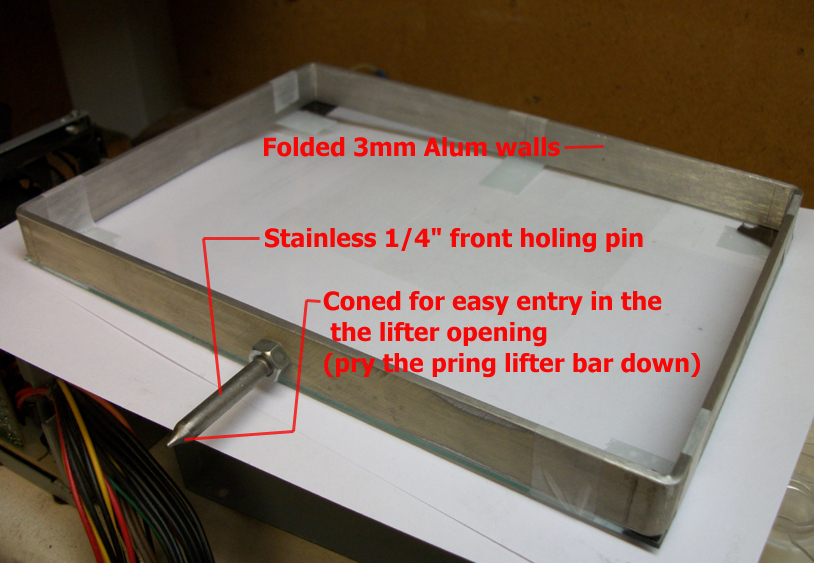
The vat with the 1/4″ Stainless lifter pin at the rear
-
-
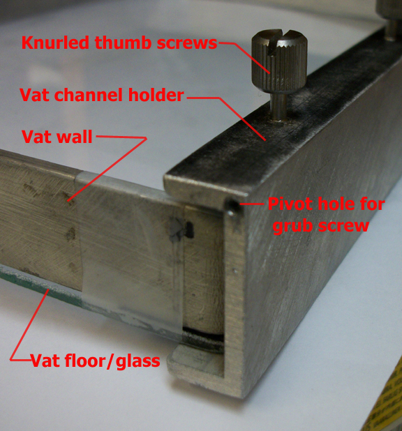
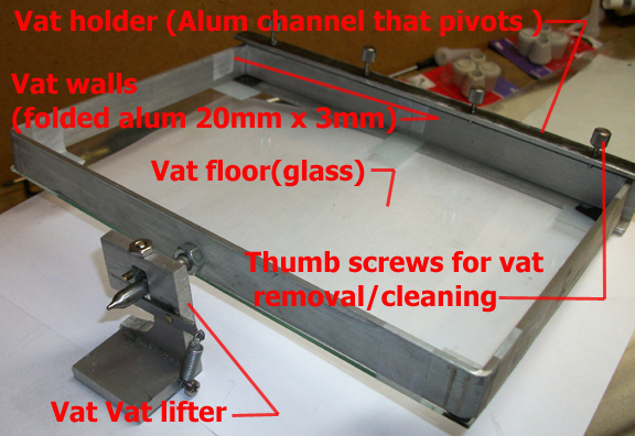
The Vat channel holder ,The thumb screws are for VAT removal and cleaning. The glass bottom is just taped on for now. I think I have finally figured out the silicone surfacing technique.I can get it down to a few microns thick with excellent adhesion to the glass.Hope it will provide a good hydrophobic surface on the vat floor for the resin.I am using pure 100% clear using silicone for now. Optical aberration and refraction and UV filtering is my main concern at this point. The layer thickness of the silicone is probably 5 to 10 microns. I will also post a short video on the technique.
-
-
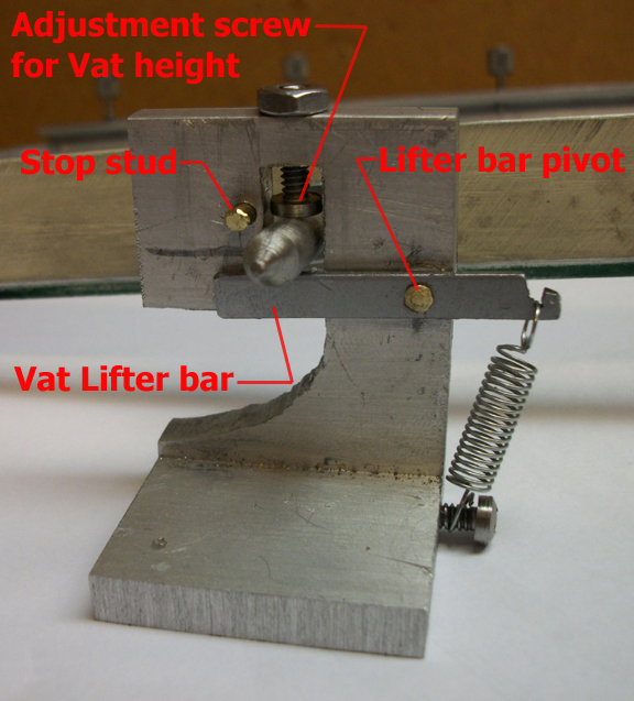
The vat lifter,Still in the rough, but I will finish it when I know it will work 100%
-
-
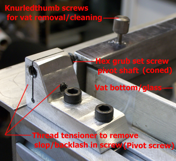
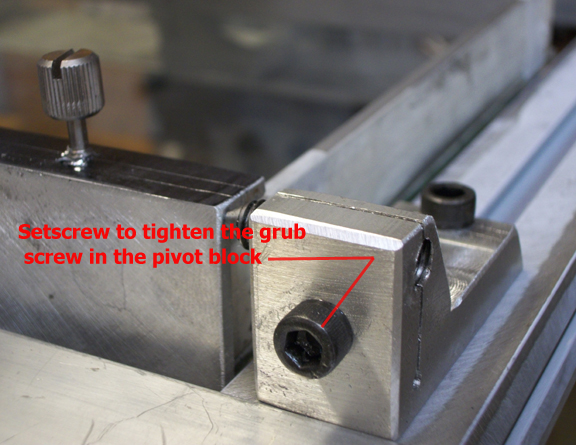
The VAT pivot block assembly
-
-
The vat pivot, front view
-
-
The vat and lifter/tilt assembly
-
-
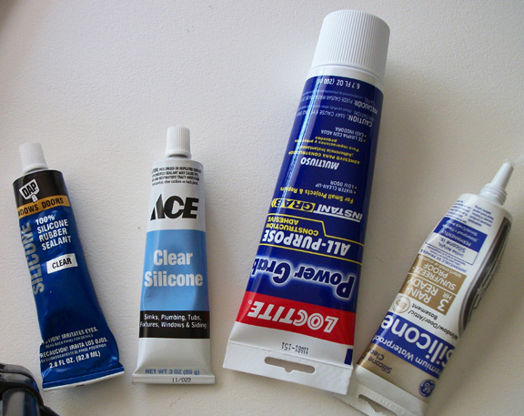
Some types of silicones I have used, “DAP” and ” ACE Brand “was the winner!”
-
-
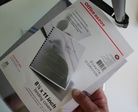
81/2 X 11″ Mylar sheets
-

-
OOPS!…..lol..Tripple exposure on the first few layers made the small centre stage stuck to walls and cracked the floor glass.(Way too overexposed…as found out later)
-
-
Shown is the small stage and cracked vat floor.
-
-
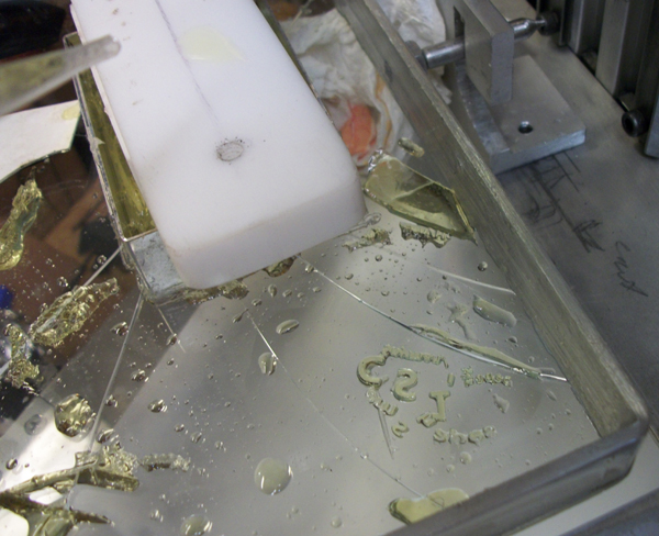
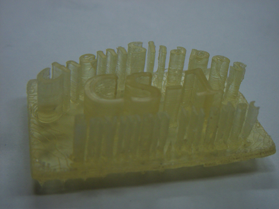
Playing with the resin revealed a lot of the mystery and un answered questionsabout the curing exposure,aggressive nature of the resin.Shown here is just the letters ChemShapes that was exposed through the puddles of resin left over on the vat floor.
-
-
Playing with the resin revealed a lot of the mystery about the curing, exposure and aggressive nature of the resin.Shown here is just the letters ChemShapes that was exposed through the puddles of resin left over on the vat floor.
-
-
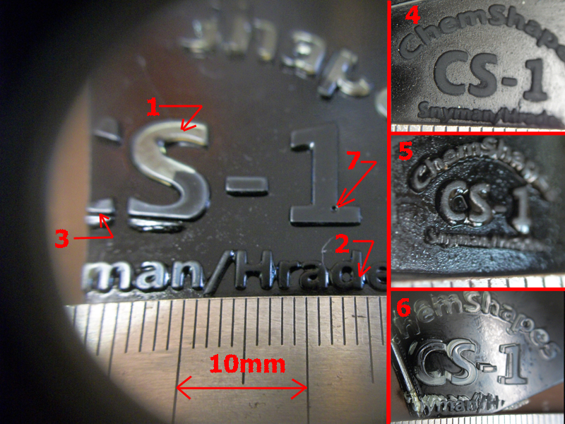
The main picture shows how nice and clean the it exposed the edges. This was on a 50 x 30mm exposure window.All compared against a mm ruler. Note some of the letter is 0.25mm wide
-
-
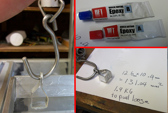
The pull test with a scale and epoxy,131 square mm gave me a pull of 1.5-2kg to pull it of the vat floor.The sideways for breaking it loose was only a few grams.
-
-
I did a strain test on the stage that went very well., 6KG (13,2LBS) pull on the side of it showed very little flex.
-
-
Aug 30 , 2011 the first model to be taken off of the stage.Still needs lots of work,but closer .
-
-
The arrows shows underdeveloped spots,wich could be because of too much uv blocker or under exposure.Because I time it manually the exposure and advance height is not consistent on every layer.
-
-
This was the longest extrusion so far, about 15mm plus the base.
-
-
Another close up note the x- scaffold support on the bottom.
-
-
Note the under developed spots at the arrows.
The VAT Floor coating:
This is where everyone have a opinion(icluding me…lol…..(and a product that he think will work best ) this one , that one …lol…makes your head spin. The final outcome will be very interesting. I cant wait to see who the final survivor will be. After reading all you input so far ,here is my 5 cent take on it:
Before we go on let us a quick look at what Ultra violet light is….UV LIGHT and how it effect our vat floor
Ultraviolet (UV) light is electromagnetic radiation with a wavelength shorter than that of visible light, but longer than X-rays, in the range 10 nm to 400 nm.
There are three types of Ultra-violet light :
UV-A : With wavelength 400-320 nm is less intense than UV-B, but is more penetrating to the eye reach and damage the retina easily
UV-B : Wavelength 320-286 burns the skin and damages the cornea and ocular lenses.Half of it does not go through window glass as far as I read and researched.
UV-C : filtered off by ozone layer
So let us analyzing the the Vat floor first ( material, thickness and filtering) and the criteria it has to meet to work with our UV exposure:
1-The vat floor ,as thin as possible.
We probably want it as thin as possible to avoid filtering . UV does not have very good penerating power and it is easily stopped by most transparent materials. Plain soda-lime glass is a BAND PASS FILTER. Most incident UV is absorbed as heat in the glass. Glass absorbs short wavelength ultraviolet light, but it does pass 350 to 400 nanometer ultraviolets wich is where most of exposure to the stage would take place.For now we will try that because it’s readily available .
QUARTS GLASS…While both standard glass and quartz glass use SiO2 as its main ingredient, the difference between standard glass or “soda-lime glass” from quartz glass (may be fused quartz or synthetic fused silica) is in the manufacturing process.
Soda-lime glass uses SiO2 and adds sodium carbonate to lower the melting point and allow working the material at lower temperatures. Since the addition of soda makes the material somewhat water soluble, calcium oxide is added to have better chemical durability. Depending on the use, other substances may also be added (lead for luster, boron to have Pyrex, iron for heat filtering, etc.)
Quartz glass, on the other hand, is usually made from pure silica (either by fusing SiO2 or from other sources of Si and O).
Thus, the purity of quartz minimizes interaction with UV, whereas standard glass have additives that can absorb or disperse UV.
Available here: http://www.sydor.com/flatopticsbasics.asp
2-The vat floor as rigid as possible , right!…OK…lol..Some argues flexibility here??..lets see.
My personal opinion : I believe that the floor , coating and walls should be as rigid and as thick as the exposure will possibly allow. You guys have to remember that “ microns ” is a small!! ,small!! distance!! any flex in the floor will eventually lead to permanent bending and bowing.Especially after 1000’s of times bending per inch. But I have to give your “FLEX” arguement credit ,that this does take place gradually over many many layers,so the next layer will just be build on the same curved plane as the previous.Parallelism wil be continued throughtout the model. For those of you that will go that route ,you will have to prove me wrong. I think I will stick to metal and glass for the vat materials for now until proven wrong.Wich brings me right to the next point..Size!
3-Size
I know we all want build big models with mini microns of resolution!..But, before you decide on a stage size (big or small) for exposure area , consider these points. (a lot have to be sacrifice to make a big stage):
1-Resolution …Resolution decays ( just like exponential scattering of a light source …inverse-square…. law of light) , it decays exponentially as it gets bigger so a 2 x 2 inch is not merely just half the resolution of a 1×1 inch,… its a lot less!.Your projector only have X -amount pixels per square inch it can give you. No matter how you look at it, ….Use it wisely and and abundandly ,apply the most pixels you can to the smallest footfprint neccesary for your model!
2-Focal height gets longer as the stage gets bigger ,so more lens distortion. Depth of field (focus plane)gets longer (harder to focus)
3-The vat floor gets big and flex much more as it gets pulled away from the floor.This goes for the stress on the glass and the horisontal beam.
4-The adhesive force grows exponentially between the Stage and vat floor
I am sure more will pop up ,and I will post more as we ran into more problems.
4-Vat floor-Hydrophilic or hydrophobic surface?
Lets define the three chemical and surface interactions that we deal with here (in simple plain english ) :
In its simplist form : The Stage should stick to the resin and the vatfloor not!. simple …huh… |:-)..Here’s a little more expanded version:
Hydrophobicity … Refer to the repellent of a element by the charge /non charge of that element towards another. Hydrophobic molecules (usually non-polar) thus prefer/attrack other neutral molecules and non-polar solvents..(Water is electrically polarized ) …..At first when I read this, of course the oil/water concept came to mind wich did put us on the right track.but..lets throw in one more action that we deal with (just to stir up the pot even more ) …lol….That is lipophilicity….huh!!??…. Yeah that’s what I first said too.
Wiki explains lipophilicity very good: …
“Lipophilicity (fat liking), refers to the ability of a chemical compound to dissolve in fats, oils, lipids, and non-polar solvents such as hexane or toluene.[1] These non-polar solvents are themselves lipophilic — the axiom that like dissolves like generally holds true. Thus lipophilic substances tend to dissolve in other lipophilic substances, while hydrophilic (water-loving) substances tend to dissolve in water and other hydrophilic substances.”
While hydrophobic substances are usually lipophilic(Oil or fat liking) , there are exceptions—such as the fluorocarbons and silicones they are hydrophobic but not lipophilic (fatty). When you open a tube of pure 100% silicone sealant ,that strong smell is the toluene (also known as methylbenzene) solvent………(also see Silicone vs silicon here)…..
2-hydrophilicity
This is basically just the remainder or inverse of Hydrophobicity . The Hydrophilic-lipophilic balance of a surfactant is a measure of the degree to which it is hydrophilic or lipophilic.
So to sum up back to plain english again:
Hydrophilicity (attrack) is the remainder of Hydrophobicity (repel) , So one should stick more than the other (a lot more) . To reduce stress on the machine parts, the stick /release ratio should have high opposing coefficients. Meaning have a good “release” on the vat floor , and a good “stick” on the stage.
We will probably at some point have different surfaces to accomodate different resins. ..Time will tell. . Chemistry is not my strong point at all ,but I know, not all resins and waxes are going to dislike just one surface.
Some fall right in between these categories and is way beyond the scope of this discusion. It can get really deep into chemistry.way beyond the comprehension of my li’l brain. We will just stick(or not stick…lol) to silicone for now, simple hydrophobic , keep it simple and see what the outcome will be. It will probably repel 80% of all resins anyway.
Other “NON STICK” Surfaces
We will also try some of the plastics and surfaces that you guys reccomended. A non-stick material that I have used in the past with much succes is …MYLAR .. It is a hard polyethylene sheet .As a matter of fact that is exactly what I am using to put the silicone on the glass vat floor . I smeer a thin layer of 100% pure “DAP” silicone (from Ace hardware) on the glass 1mm thick, then cover it with a MYLAR sheet .(Do it within seconds to prevent the evaporation of the toluene ) Squeeze out all the bubbles .Then take the silicone layer (sandwiched between the glass and mylar) down to a few microns.I do that by pressing and iron with a flat cold surface object like a machined metal block or cold clothes iron . After a hour pull of the Mylar off and you are left with a crystal clear shiny surfaced silicone layer stucked to the glass like crazy! .I have tried many ways before ,But this one seems to be the only way that you can get the toluene to catalize the silicone. If you leave it just thinned out and exposed (without mylar) it never cures properly. I have tried probably 5 different kinds of pure 100% silicone but “DAP” and the “ACE Hardware brand” is the purest ,clearest and finest ground. ACE Hardware sells both.
The clear Mylar sheets can be obtained at any Office supply/stationary store as binding covers (some are perforated). get the extra thick ones ,as it gives a much more even surface.I was surprized how smooth and clear the silicone surface was.
Links for good “Non-stick” surfaces
http://integument.com/antigraffiti.html
July 25,2011
Aug 3 ,2011
I finally got around to post some pics of doing the vat floor.
After many ,many attempts with many different aproaches and many diferent kinds of silicones, I got this this method down to where it gives me consistent and very satisfactory results:
1-I Have used about a dozen different kinds of silicones.The one that I found to work the best is “DAP”. 100% PURE SILICON”.For some reasson it just flows smoother and the consistency is just right.Maybe they use a different kind of toluene…? . Another one that works good is the ACE HARDWARE Brand.

Some types of silicones I have used, "DAP" and " ACE Brand "was the winner!"
2-This Mylar /Silicone idea stems way back to a old DACRON / EPOXY technique that’s used on Experimental Aircraft. You press a dacron sheet on a still “wet” Epoxy surface to soak up any unnecesarry and extra epoxy and it gives you a almost type of knurled surface when the dacron is peeled off after the epoxy is set.
So I figured ,Mylar will give me a super nice glossy finish. I just did not know what the toluene will do to the mylar. Anyway to my surprize the mylar helped “catalyze” the silicone to a cure.On previous attempts ,before I used the mylar, I would try and smeer the silicone to a very thin layer over the glass,but the silicone never set to a dry/hard state,it always stayed sticky.The toluene would evaporate too fast for the silicone to catalyze or set to a dry/hard state.
So the MYLAR sheet was the solution to two problems,One was the curing (It was just thick enough for the toluene to slowly evaporate.) and the other was obtaining a shiny surface,it also helps to even out the thickness of the silicone strata.
3-What do we need ?
3a-Thick MYLAR Binding cover sheets(81/2 x 11″), $10 for (20x) of them at Office Depot,Get the thickest you can find.
3b-Tube of “DAP” or “Ace Hardware” Silicone
3c-A Straight edge that has a little flex to it.
3d-Skotch tape,to mask the edges(if you want)
3d-A thick piece of posterboard to work on.
3e-VERY IMPORTANT!……,A dust free environment……..remember one spec of dust will block out one pixel on your model (even more if you print small)
3f-Acetone ,soap and water. paper towels (a full roll).
3g-The VAT Glass floor and the vat frame.

81/2 X 11" Mylar sheets
4-Start by washing your hands at least twice(WITH SOAP) to get rid of all skin oils.Clean the glass, first with Acetone(as clean as humanly possible and NEVER touch the surface of the glass),Now wash it with dishwashing soap and hot water,dry with papertowels until it starts to squeak.(I used up about 20 paper towels in the process.).Also make sure to use the most lintfree papertowels as possible.
5-Tape the glass sheet to the posterboard,go in about 2mm around the perimeter of the glass.This does two things,it holds the glass down on the board but more importand it keeps the silicone from squeezing in under the glass,you want to keep the bottom of the glass now clean until all the silicone is set.
6-Start with a nice blob right in the middle of the glass. Use your judgment ,it should be enough to give you a layer of at least a layer of 10 or so microns over the whole surface of the glass.
7-Put the mylar sheet on top .Gently start to squeeze from the contre outwards until you get a 3″ diameter blob .If any bubbles is trapped at this point lift the mylar all the way to bubble and gently iron it out with your fingertips.Dont use your nails or any any sharp edges ,it will bend the mylar sheet.
ALL BUBBLES SHOULD BE OUT BY NOW! I there is still any trapped ,clean and start over again.
8-Keep ironing all the thick spots outwards evenly with your fingers until the sislicone is about a 3mm thick.Now switch to a straight edge with rounded corners that flexes a little.
keep working the the silicone outward with the straight edge.Make sure to cross over 90 degrees in all direction, go down evenly until you feel that the silicone is not moving anymore and you should be right 20 to 40 microns thick now .Very important! .
9-The mylar will probably have a lot of stains of silicone and scratches at this point. Don,t worry about that. WHAT IS IMPORTANT IS THIS: Make sure at this point you did not press any divots in the mylar,Divots can still be somewhat be rescued at this point but bubbles not.The corners have a tendancy to suck bubbles in under the mylar.
10-After your satisfactory ironed surface, leave at least 24hr. to dry and catalyze (and leave it alone now!).If you lift a corner when its still wet you will totally ruin the surface. After 24hr. It wil peel off very easy. And you will be amazed at how shiny that silicone can get!!
11-After the glass is done .Line the inside of the vat walls with a thin layer of silicone ,Smeer the silicone with your finger until completely covered then put your vat frame upside down on the posterboard .
Squeese a bead of silicone alongs the frame edge (just enought to get a good seal) .Lleave the frame on the Board upside down.VERY CAREFULL TO NOT GET SILICONE ON THE GLASS NOW!! ,Lift the glass and put it down on top of the frame with the silicone surface facing down.The reason you glue this upside down , is so you can see if the silicone bead seal and fill in the surface between the frame and glass.It is very easy to see it through the glass.If there is any shortage at some spots where it didn’t fill in.Press some in with your finger from the ouside, BUT DO NET GET ANY SILICONE ON THE BOTTOM SURFACE OF THE GLASS . Silicone adheres tenaciously to glass and can not be cleaned afterwards.Leave for 24hr.
You can trim any acces silcone now and even wash the vat floor silicone surface now with a soft spunge and soap,Take care not to put and scrapes in it though…I will also post a video of the hole process soon…
Aug 12, 2011
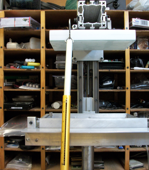
I did a adhesive release test for the vat floor with small piece of U-aluminum bracket and a pull scale. The bracket had a hole on top to pull straight up.

131 square mm gave me a pull of 1.5-2kg until it released of the vat floor.The sideways for breaking it loose was only a few tens of grams.
I glued it with a 2- part 5 min. epoxy to the vat floor. It gave me pull of 1.5 -2kg before it released.Wich had me kinda woried.The side ways pull is only a few grams,wich tells me that it is mostly suction/vacuum I am pulling against.I tried it five times with about the same results .(As it will later turned out , the resin ‘s adhesive strength was not near as tenacious as the epoxy.)

I did a strain test on the stage that went very well., 6KG (13,2LBS) pull on the side of it showed very little flex.
Aug 19 ,2011
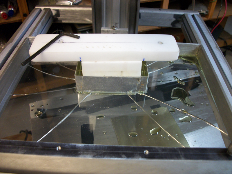
I just love research and development its full of surprises around every corner….. I couldn’t wait for the sudan 1 ( on backorder) so I mixed up a batch of HEXANEDIOL DIACRYLATE and PHENYLBIS (Dr Fangs) to try and and at least put all the theory to practice..(And play of course)…. Whell this was a very ,very educational exercize.The following test I have done manually and advanced the stage up by hand. It was mainly to try the vat floor silicone’s hydrophobicity to the resin.And also get a feel for the cure time.I had no intention to make a super high resolution model.This was just an experiment,(that went very well).I also pulled of a lot of little test cured plates of the vat floor by hand to get a “hands on ” feel for it. It is very difficult to determine the strenght needed if a high torque stepper does the job.
I made a small vat inside the big vat and build a small stage to replace the standard one.(see pic)

OOPS!.....lol..Tripple exposure on the first few layers made the small centre stage stuck to walls and cracked the floor glass.(Way too overexposed...as found out later)
So here is what happened:
After filling the little vat , I started of 0.25mm (250 microns)above the vat floor with the small stage. Now keep in mind we have a 2000 Lumens projector focused down to a 50 x 30 mm image (window) . Exposed for 8 seconds,advanced yp another layer and did it again( for a few times) .Still all was well. But little did I know I was just bending the glass of vat floor as I was raising the first few layers.(Also for my first trial run the room was somewhat dark dark, because I had no idea how that stuff will react to ambient light) , So at the 3rd try or so,I heard the snapping sound of glass….see pic. ……..It could bend no more..
The conclusion:
With no UV inhibitor in it , the first layer was way over exposed ,the light probably went up the sides of the vat and glued the stage to the side walls of the little vat.(here is another lesson: Do not make your stage material out of any white or translucent material……Then to make matters worse I overexposed the 2nd and 3d layer without the vat ever releasing the floor(meaning I fried the first layer with 3 over exposures).

Shown is the small stage and cracked vat floor.
So after the cracked floor I switched on all the flourescent lights (GE.cool white) in the workshop re-evaluate what happenend and then started playing (exposing) with the rest of the batch on the vat floor .

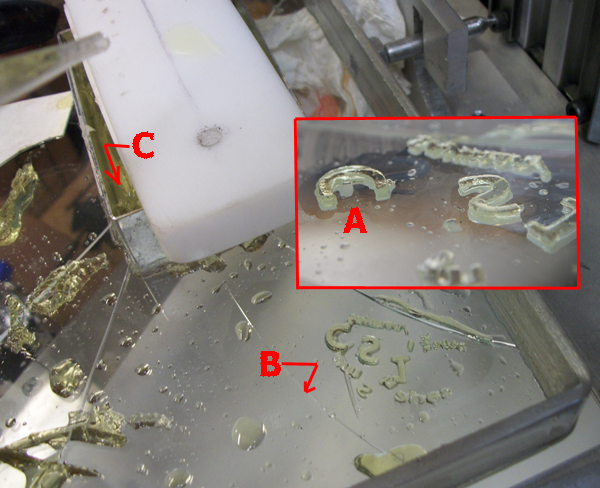
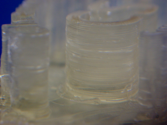
Fig.Vat-Playing with the resin revealed a lot of the mystery about the curing, exposure and aggressive nature of the resin.Shown here is just the letters ChemShapes that was exposed through the puddles of resin left over on the vat floor.
See fig. VAT
A-The Capital C wich is 1mm thick
B-The crack in the floor
c-The cured vat walls

The main picture shows how nice and clean the it build the edges. The resin is a light transparent see-thru yellow on black/plate. This was on a 50 x 30mm exposure window.All compared against a mm ruler. Note some of the letter is 0.25mm wide
So What have I learned from this:
1-Number one…The CS-1 Is doing exactly!…exactly it’s job designed for, It works awesome!.It is way strong enough and rugged enough to handle a big exposure. As far as the cracked glass….aaah! no biggie , I can make hundreds ….and it doesn’t cost me hundreds of $ either. )
2-Over exposure wil lead to damaging the glas(break…lol…..) and burning the silicone surface white/milky (Yes It gets hot man!, At the end of the test I thought I might as well finish of the floor and super over exposed it. I smoked it good! It only took about 15 seconds in 1.5mm of resin. …That stuff is aggressive!
3-it look like the magic exposure time is about 3-5 seconds on a 50 x 30mm window for 1mm thick resin . (I will try thinner on the new vat floor).
4-The hydrophobic silicone surface works fantastic!! with just the right exposure time it slips right of,pushing it sideways,It is the vacuum in the upwards pull that makes it stick more.
5-Dr fang’s recipe works very good,almost too good…lol.
6-This stuff gets hot!
7- The stinky fumes are bad, guys you were all right! …. this recipe does call for ventilation or air extraction.Granted that it would not be normal to smoke it like I did . I only worked with a 150 sq mm surface.(I can imagine a 2 x 2 foot section) . Hope the other resins are better.
8-I was really surprised at burning the vat floor a little milky at some spots.(wich was not a good thing).But then on the other hand, those temperatures should never be reached otherwise shrinkage would be a real problem.
9-Use eyeware,…lol..At one point I was rubbing the corner of my eye,the slightest invasion in your eyes burns like fire.
10-After I switched on all the flourescent lights the ambient light it had really no affect on the resin.I did not know what spectrum all the flourescent bulbs were, thats why I started of in the red room first.
11-You definitely need a UV inhibitor/blocker , when those radicals run free for all ,those molecules just have an grand o’l time , a molecule feeding frenzy ,and the reaction is way too aggressive.
9-You can cure a thick layer probably about 3-5mm thick (or more) without an inhibitor.
Once it starts it goes quick.You can probably do even a lot thicker than that even ,But for now , I don’t want to waste too much resin ,It is a little on the expensive side just to waste.
10-Another thing That I realised was that I have to switch to a completely dark opaque /non translucent stage material. That 2000 lumens light beam penetrate the white plastic stage block, It lights it up like a Ice castle at Chrismas!. (not good for those hungry molecules.)
11-So all in all This mornings trial a was very ,very good learning lesson. The resolution is awesome and I can shorten my cure time.The silicone works great ,so the only variable that did not work was the release.
In the future I will have to raise it up more(or lower the vat more) past the release height,Then bring it back down again to make sure it broke completely.The “break loose ” height will of course be determined by the exposure time…….It’s a ” wich comes first, chicken or egg” thing..
Aug30, 2011
Today I combined two previous batches I had mixed before .It contained the following:
1-HEXANEDIOL DIACRYLATE (for faster reactivity)
2-PHENYLBIS
3-UV-24 FROM CYTEC (as a uv blocker)
4-TRPGDA WICH IS NOW TPGDA (for lowering viscosity)
5-TMPTA (for better flexibilty)
5-ADDITOL -TPO initiater ( This was mixed in with the first batch,and had not much of a catalysing reaction at all,I think it was for the wrong spectrum). I also think the PHENYLBIS caused most of the reactivity here is the “cake I baked or rather “extruded” .
This time my main goal was (1)… to get enough developed..andto extrude it out of the resin , and (2) …to be able to remove it from the stage when I was done.
I did not go for high resolution neither sharp edges this time (as before) . I know the CS-1 can do that now. AS matter of fact I layered it in 0.25mm layers (250 microns). wich is really thick layers. You can also see on the black and white images that did not utilize all the pixels either.(See black and white images).
I did succeed in both.I also overcome the tenacious adhesion strength of the Hexanadiol Dyacrylate to the vat floor by addin other polymers. I also added a sacrificial scoffold support this time for the main model. It is use to break the main model loose from the base

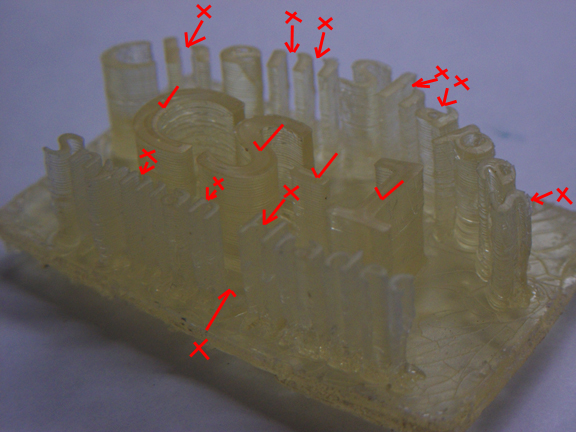
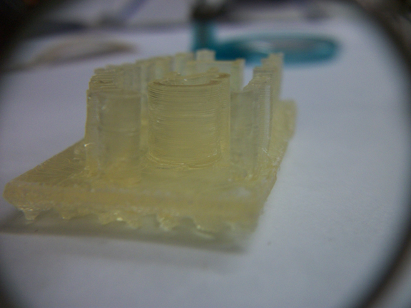
Aug 30 , 2011 the first model to be taken off of the stage.Still needs lots of work,but closer .

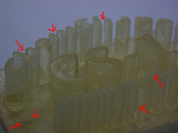
The arrows shows underdeveloped spots,wich could be because of too much uv blocker or under exposure.Because I time it manually the exposure and advance height is not consistent on every layer.

This was the longest extrusion so far, about 15mm plus the base.

Another close up note the x- scaffold support on the bottom.

Note the under developed spots at the arrows.
There is still flaws in the lettering and some spots that did not develope. Probably because some layers were thicker than others(I still advanced the z-axiz by hand to get a feel for the adhesive strength of the resin.)This was only my second try , and at least this time I got the model raised/extruded out of the vat .Also,even though I had to cut halve of the scaffolds off( it was molded together) ,The other halve was perfect and would have snapped off easy.
I had to brake almost all of the previous models of the stage, cause I could not build a scaffold supports for the main model yet.
This trial run definitely proofed some more success ,especially with the addition of the TPGDA and TMPTA AND THE CYASORB UV-24 by CYTEC ,There was much les cohesive forces involved,…(I pushed the vat down by hand to feel the force) …,And this recipe was a lot more gentle on the Silicone floor too.
(Speaking of the reaction of polymers on rubber,….I ran across …..these awesome tests….. they did on rubber gloves and polymers)
Here is some points that still needs attention:
1-The UV light is still not blocked enough ,it went through the flat base and into the suport scaffold and formed a solid spot in the middle (where the light is the most intense).
2-The thin widths of the letters underdeveloped. (see red arrows)
But to conclude , I would say this was definitely another advancement in chemical recipe , mixing, developing and extrusion.
I am going to switch to new glass stage again.
At least now we have elimated these few variable:
1-we know that the vat and stage works well together
2-we can extrude this polymer recipe
3- The previous test proofed to have high resolution.
One variable that wil always linger is the duration of exposure ,for this one , 8 seconds seemed to the the golden rule,For the very first batch (Dr. Fangs) it was 3 to 4 seconds but that was on a very small image 30 x 50(intense light exposure)
So my next goal is to combine all three ,stregth, high resolution and shorter duration per layer.
Once I have that established i will focus on the shrinkage and color.
Sept 1 ,2011
Here are steps I followed to build the Model shown above:
1-For the firts layer of any model you want to “Grow” I thought it would bewise to have the very first few layers as a solid image area. This will give us very good adhesion to the the stage. So I exposed a full image area of 3 layers.
(See Model image #1) .This startup base would also be good for the Sacrificial Scaffold Support( SSS) to hold onto ( see image #2) , three layers deep @ 0.25mm per layer. Used Image #1 that was just a plain white base .

MODEL Image # 1 ,for the first 2 layers.
2-The… Sacrificial Scaffold Support ..(SSS)…came next.(see image #2) This is also something to develop a feel for.It has to be strong enough to hold the model in place,sturdy an rigid,but also thin enough to break the main model loose from the base ,otherwise the model have to be destroyed to take it of the stage. This was built with” cross a section “.You can use prety much any shape for the collumns,as long as it can be sacrificial. (see image #2) About 20X Layers @ 0.025mm=5mm high`

MODEL Image # 2 The cross scaffold support .Design to break loose.
Without the right amount of UV blocker I got over exposure through the base of MODEL image #3 so my SSS was “grown” together in the center area (Had to use a Hack saw to cut off). but the SSS around the outer perimeter worked fine.
3-Now it was time to start the model. I did just a plain block base for the lettering to stand on, and used used MODEL image # 1 again
Did about 15 layers again @ 0.025mm .
4-Then started the lettering ,Used MODEL Image # 3, for about 50 layers wich gave me about 12 mm or so. mabe a littlle higher. I could have kept going at this point to 300mm if I wanted to.

MODEL Image # 3 ,The text
5- the whole proces took probably an hour (manually)
NOTE:
I am going to post the rest of the chemical research and development in the CHEMISTRY menu on top , look under RESIN or
… Click here…. ( Just to keep information in their right categories) .I will focus on the UV Blocker first cause UV inhibition causes problems in a few areas :
1-under/over developing
2- duration of exposure
3-Penetration
4-Crazing of base layer
All of these in turn will require different settings and formulations for different size images because of the
…inverse-square…. law of light,All it means is that the further you go away from your light source the weaker and more scattered the lightrays are.Wich have to to compensated for.
I will also post the images I used for this last model too..


Recent Comments