CS-1 Host Software Win32 EXE!

Ok… it’s finally here… a self-contained EXE file for our current CS1 Host software.

You can download it here: CS1 Host Software for Windows 32 bit

I’m adding these download links to the sidebar as well, for easy access. New versions will replace old ones, so to download a newer version, just use the same link!

Download, play with it and let us known how it goes… Keep in mind this is just a pre-release for distribution test purposes, so don’t expect it to be functional yet!


CS-1 Host Software OSX app!

I finally got it! An self-contained app for OSX of our host software!

Just uncompress it, and double click!

download it here!

Windows EXE file coming next!! 😉

Realtime Slicer proof of concept using GPU

It’s being a while since my last update on our software, but I got some exciting progress to report at least…

Images are better than any description, so check it out for yourself:

httpvh://www.youtube.com/watch?v=ydT8HXTou2U

This video shows my first successful test on slicing a model in realtime using GPU shaders!

I’m cleaning up my code right now and you should be find the first public version of the CS1 host software on our github by today afternoon!

https://github.com/hradec/chemshapes

or you can download a “zipball” of it directly by clicking here

I invite everyone to download it and give it a try! I really wan’t to known how the GPU code will behave in different computers with different setups, to see how feasible it will be to rely on GPU for our base software. From what I known, GPU shaders is something very common on hardware these days, and it has being for a few years now, so I’m hopping you guys computer setup already have a reasonable good video board that will support GPU shaders. Maybe not as fast as a computer game would need, but fast enough to slice and display slices in realtime. But to confirm that, I need you guys to test the software asap!

To download the software, theres a big “DOWNLOAD” button on the github page. Download it as “.zip”. After uncompress it, go to “host” software, and if running Windows, just double click on:

“Click here to run Chemshapes Host Software.cmd”

and it should launch it.

If you find any issues, bugs or suggestions, please report it on this page: https://github.com/hradec/chemshapes/issues

The host software can read booth .obj or .stl files… please try it out and let me known!

The viewport camera has some issues, like not automatically adjusting the frustum and clipping planes when loading new geo, so keep in mind that you may have to zoom in/out to see a model you just load, in case it won’t show up automatically!

Apart from the slicing demo, the communication with the electronics also works, and it connects successfully with  the reprap Sprinter firmware, and should connect fine with any other reprap/gcode compatible firmware over serial port.

If your electronics is arduino based, I strongly recommend you to install our fork of the Sprinter firmware, found at:

https://github.com/hradec/Sprinter

have fun!!

CS-1 PCB’s and schematics

This page was last updated on Jun 18, 2012 

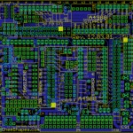
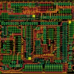
Eagle Cad files of the CS-1Top copper trace trace layout (Done in EAGLE CAD) below:


Bottom copper trace trace layout (Done in EAGLE CAD) below: 


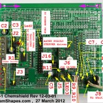
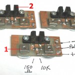
Populated view below:


CS-1  Assembly manuals:

Main Cs-1 Assembly manual here:

 Chemshield_assmbly_ instructions.


 CS-1 30 way Ribbon Cable  Assembly here:

Assembly_instructions_ribbon_harness_Rev_12_06_12


 CS-1 Opto Interrupt PCB’s assembly manual here:

WOPTO_INTRPTS_ASMBLY


CS-1 PIN LAYOUTS_Apr8_2012

Mach3 macro for controlling Powerpoint

Here is the latest version of the macro that allows Mach3 to open Powerpoint, display your individual slices/slides and move your Z axis into position for each build layer. This solution is only good for slice files that are bitmap files or any format that can be loaded into Powerpoint.

To setup the slides show:

Open PPT and insert a new photo album. Load your slice files. Note: for some reason, when PPT loads a series of images, it puts the last file at the top of the list then continues the order properly. For example. if you have 100 images in your sequence, your order will look like this:

image_100.png
image_001.png
image_002.png
image_004.png
and so on…….

Fig1_A Don’t know why PPT does this but it’s annoying. The first solution would be to select image_100.png and move it down to the end of the list (in the PPT dialog) This could be a pain if you have to move it down, one click at a time, to the bottom of the list.

The easy solution is to go into the folder that contains your slice files, duplicate the last image and rename it image_101.png. Then when you import your slides, you just delete image_101.png, which will be at the top of the list. The rest will be in numerical order.

Fig2_B Under album layout, set picture layout to 1 picture. This will center the images and keep them aligned.
Fig1

Click create. You will see that the first slide is blank and that’s fine, do not delete this slide. Now just set the background to “black” for all slides. Save as a .pps file not .ppt

Here is the macro for Mach3:

[sourcecode language=”vb”]

Option Explicit

‘Change the constant values below to suit – make sure your Powerpoint file is .pps
‘*****************************************************************
Const ppFileName As String = "C:\My Documents\my slideshow.pps"
Const ZStartPoint As Double = 0.0 ‘where Z starts from
‘*****************************************************************

Dim numSlides As Integer
Dim exposureTime As Integer
Dim ZIncrement As Double
Dim s As Integer

‘ User inputs for variables

NumSlides = 15
exposureTime = 8000 ‘ in ms
ZIncrement = .005

Dim objPPT
Dim objPresentation

Set objPPT = CreateObject("PowerPoint.Application")

objPPT.Visible = True ‘ set to display on top

Set objPresentation = objPPT.Presentations.Open(ppFileName)

Code "G90" ‘absolute distance mode

Code "G0 Z" & ZStartPoint ‘start Z at wherever
While IsMoving()
sleep 10
Wend

Code "G91" ‘incremental distance mode

SetFeedRate(5/60) ‘ feedrate 5 inches/minute set as appropriate

For s=1 To numSlides

objPresentation.SlideShowWindow.View.GotoSlide (s) ‘show the next slide

sleep exposureTime

objPresentation.SlideShowWindow.View.GotoSlide (1) ‘ show slide 1  blank slide

Code "G1 Z" & ZIncrement + ZIncrement + ZIncrement + ZIncrement + ZIncrement + ZIncrement + ZIncrement + ZIncrement ‘lift Z a couple of tads
Code "G4 P1"
While IsMoving()
sleep 10
Wend

Code "G1 Z-" & ZIncrement + ZIncrement + ZIncrement + ZIncrement + ZIncrement + ZIncrement + ZIncrement ‘lower Z a tad
While IsMoving()
sleep 10
Wend

Sleep 1000 ‘ this value adds a delay before the next slide is displayed

Next

Code "G90" ‘back to absolute distance mode

objPresentation.Close

objPPT.Quit

[/sourcecode]

Copy this text (using the icons that show up when the mouse is over the code) and save as M800.m1s
put it in your Mach3 macros folder (in the profile you are using) then type M800 on the MDI screen. That’s it, You can now adjust the parameters in the macro to suit your machine and resin mixture. Let the experiments begin!

This has been tested successfully with Powerpoint 2003

Thanks to John T for the macro mods! This macro is fully functional but we still want to add more features, I will post updates as they get completed.

Jon
CSR-1 ,UV Rapid shot modeling

The CSR-1  is only in conceptual stage and pretty much a hypothesis for now. The concept   carries a lot of merrit and  hold it’s own category because nothing like this has ever been attempt or build before. ChemShapes is the only company that we know of that is in development of  this technology .It is called the  “RAPIDSHOT” This method is truly unique and will put ChemShapes on the forefront of rapid prototype technology. It will be called the (CemShapes Rapidshot) ,   CSR-1 Model.   The CRS-1  will do a one time  8 to 20 seconds cure for for  a 1 cubic foot model. then just like the CS-1 post curing.

What is it?

more coming soon.

UV cured modeling

Last updated JUL 14, 2011

This is a very controversial subject defended by a lot of  purists. Here is our take on it.

For most application the Ultra Violet or visible light curing  method is by far superior and much faster to any other rapid modeling methods. The name 3d-printing is actually a misnomer. a Better  title for it is ” Layered UV cured modeling” . Even though this method uses resin for every layer buildup it is not mechanically applied at every layered  level. Becaus it is a liquid at low viscosity ,it uses gravity to fill the building  gap for the next layer of curing. For that reason we do not categorize it as deposition modeling . It has great resolution , and uses  minimal moving parts.

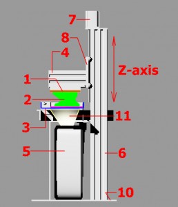
Fig. 1. The basic concept of UV light curing,1-Stage (building platform),2-The model being build,3-The Vat containing the resin,4-horizontal beam,6-Main Z-Axis collumn,7-Stepper motor,8-Carriage plate,10-Base,11-Projection beam

http://en.wikipedia.org/wiki/Rapid_prototyping

So what is a rapid prototype  modeling by light projection  and how does it work?

The purpose of it is to rapidly ( a few hours)fabricate/grow  an exact replica of a 3 dimensional computer aided design drawing(CAD). It is normally a conceptual or working  model for the industry. Scientists ,architects,dentist ,jewelelers etc. make very good use of it and for the first time this will now be available to the hobbiest,the D.I.Y’s  and tinkerers . Any type of model can be build with it with no limitations to undercuts ,hollow structures or curvature. It builds a model in a 3 dimensional  hard durable  solid layered  format in resin ,rubber or wax. (now other materials also became available). The model is build upside down with the base attached to the hatced blue platform.

The software interface (see link below) starts  the process by slicing a 3d CAD drawing into thousands of horizontal sliced layers and generate a photo image for each  cross section in a seqential order. For example if the model was a sphere ,the images would start as a small tiny round white dot on the bottom and grow sequentially bigger per layer until it gets to the center  slice(the biggest) .Then it will get smaller again (per layer) as it goes to the top of the sphere. . The last sliced image wil be small again.  Each image is used to seqentially build  a one layered cross section at a time. Each layer is formed by hardening  a layer of resin by the printer  as decribed below:

Refer to the above illustration Fig. #1 : A Light curing resin  (usually Ultra violet(UV)  sensitive) is poured into a shallow  square vat/container (shown in blue color).The bottom of the vat is made of clear glass .  A building platform  (Yellow) is lowered into the liquid resin until it almost touches the bottom glass (hairline space above). A projector projects the first image sliced (cross section #1)  of the 3d CAD drawing in white light (or uv) through the glass onto the building platform surface for about 8 seconds. As the thin sandwiched layer of resin between between the glass and the building surface recieves  the light, it cures to a plastic consistency(polymerize). This first layer is importand ,It forms the base of our model wich is now glued to the building platform surface. The printer  stops projecting and  let the computer know to move the platform up another hair thickness (0.01mm) .The printer calls for the next image and projects the next layered image.The process repeats itself over many thousands of times with a new image every time…….. Layer after layer the model is build up ( like a thick stack of paper)  to form the solid model.

This process continous until the whole model (green) is extruded from the resin vat.The model is build upside down, as it extrudes from the base first.

A highly  detailed model (high resolution) of 2 inches high (50mm) usually consist of thousands of layers. Needless to say that the whole process is  computer controlled and can take up many hours to build a small 2 inch model.

___________________________________


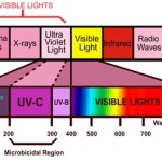
Ultraviolet (UV) light is electromagnetic radiation with a wavelength shorter than that of visible light, but longer than X-rays, in the range 10 nm to 400 nm.

There are three types  of Ultra-violet light :
UV-A : With wavelength 400-320 nm is less intense than UV-B, but is more penetrating  to the eye reach and damage the retina easily

UV-B : Wavelength 320-286 burns the skin   and damages the cornea and ocular lenses.Half of it does not go through window glass as far as I read and researched.

UV-C : filtered off by ozone layer

Here is the a the lightwave  spectrum ,we are going to focus on the Ultraviolet


The Electromagnetic VISISBLE LIGHT Spectrum

Fig. 1 The Electromagnetic spectrum

***********************************************

Other links:

1-TYPES OF RAPID PROTOTYPING

2-….Here….. is a good link if you want to dig really deep in the definitions.

Companies that does RP modeling

1-http://www.redeyeondemand.com/Materials_PolyJet_photopolymers.aspx


Rapid prototyping by deposition

We will include all other deposition methods on this page. Almost  all rapid prototype method includes the depositing or build up  of  a material added in a layered buildup of some sort. The most comon ones are:

1-…3-Dimensional Inkjet Printing (mostly pure wax buildup),

2-Fused Deposition (mostly extruded waxes, glue and plastics)…In this method the one layer gets fused by heat to the next layer by a microscopic plastic, glue or wax  extrusion from a round or square nozzle.

3-Laminated modeling  by  layering (mosty paper layering)

4 -Laser Sintering (layered powder,mostly metal, deposition bonded by a micro laser ). 

5-Jet printed resin on layered Powder  deposition…..Even though this process is very similar to laser sintering(without the laser)  we will categorize it by its own .It uses a curing resin printed printed on top a layered  powder buildup. Big advantage of this method I can be done in colors.

UV web links

Last updated MAY 16, 2012

Tutorials:

1-http://www.emeraldinsight.com/journals.htm?issn=1355-2546&volume=15&issue=1&articleid=1769074&show=html

1-Prof .Nicholas Fang

2-http://mrsec.wisc.edu/Edetc/nanolab/3D_print/index.html

3-http://www.enerconind.com/mediaLib/stml/webinars/Enercon-Promoting-UV-Flexo-Ink-Adhesion-for-Flexible-Packaging.pdf?ext=.pdf

4-http://www.uvtech.com/web%20page%20material%20and%20library/How%20to%20formulate%20UV.pdf

5-http://www.cepe.org/epub/easnet.dll/GetDoc?APPL=1&DAT_IM=02001C&TYPE=PDF

Chemistry and suppliers  links:

UV Resins,waxes ,epoxies,rubbers and ink:

1-

2-CYTEC,  ADDITOL

3-http://www.beachcreations.com/product_info.php?pName=sun-cure-uvc-2000-uv-catalyst

4-http://www.specialchem4coatings.com/news-trends/displaynews.aspx?id=523

5- CYTEC

6- http://www.deco-coat.com/uv.html

7- UV INKS

8-http://solarez.com/productsnew/zerovocqt.html

9-http://www.crcnetbase.com/doi/abs/10.1201/9781439827468-a1

10-http://www.threebond.co.jp/en/technical/technicalnews/pdf/tech45.pdf

11-TRPGDA-http://www2.basf.us/rawmaterials/pdfs/TPGDA.pdf

12-http://onlinelibrary.wiley.com/doi/10.1002/app.20422/abstract

13-http://www2.swaylocks.com/forums/uv-vinylester-answers

14-http://www.dymax.com/

15-http://www.dsm.com/en_US/downloads/11122_Data_Sheet2.pdf

16-http://www.huntsman.com/advanced_materials/Media/FLYER_SL7870_LoRes_last.pdf

17-http://www.threebond.co.jp/en/technical/technicalnews/pdf/tech45.pdf

18-http://www.thefreelibrary.com/New+UV%2FEB+raw+materials.-a0133009252

19-http://www.radtech-europe.com/files_content/krendlingerpaperdecember.pdf

20-http://bucktownpolymers.com/

UV  Inhibitors/absorber/blockers/stabilizers:

1-http://www.chemshapes.com/wp-admin/post.php?post=295&action=edit&message=6

2-http://www.norquaytech.com/uvstabilizers.htm

3-http://www.mayzo.com/uv-absorbers.html

4-http://www.functionalpolymers.basf.com/portal/basf/ien/dt.jsp?setCursor=1_556325

5-http://www.peakcandle.com/products/UV-Inhibitor__AD1001.aspx

UV Patents:

1-http://www.freepatentsonline.com/y2007/0093598.html

2-http://www.freepatentsonline.com/5779779.html

UV TOOLS

http://equipment.loctite.com/productLineDetail.cfm?pl=19

Beakers, graduated cylinders,pipets, scales etc.

Glass:

1-http://www.sciplus.com/index.cfm

Scales:

http://www.harborfreight.com/digital-pocket-scale-93543.html

Links of similar interest :

1-medical

Model CS-1,Rapid prototype shaper/printer

This page was last updated Aug 13, 2011

————————————————————————————————–

Model CS-1

We have come a long way Since we kicked off with the SNYGRO. It all evolved into the Our first model The ChemShaper(CS)  model 1 or  Model CS-1 .

we are not going to post the whole evolution Of the CS-1 . You can read more about it  here.  , the history and where it was born.

We will just post the final stages  and troubleshooting that we do .

Here is where we left off:

The CS-1  project will be based on a digital light projector solidifying a photo sensitive wax/resin  layer on a growthplate (as described above.). What makes our printer stand out from the rest is the fact that it is MODULAR. Meaning ,in just one printer you can have much  more versatility and choice in stage (building platform)  size and height .

 This MODULAR aproach will allow the resin vat to be raised or lowered for bigger or smaller models. (See fig.)
 

You overcome the limitations of  one small fixed growth cubic volume. One thing to keep in mind is that as you enlarge the projected area you loose a lot of resolution (see VAT  construction). The quality of the resolution will be relative to the size of your stage.

The main reason for this aproach is versatility.One  printer can cover a much wider field of interest in the industry, from the jewelers that makes a small 1″ rings to a sculptor that makes  18″ sculptures.

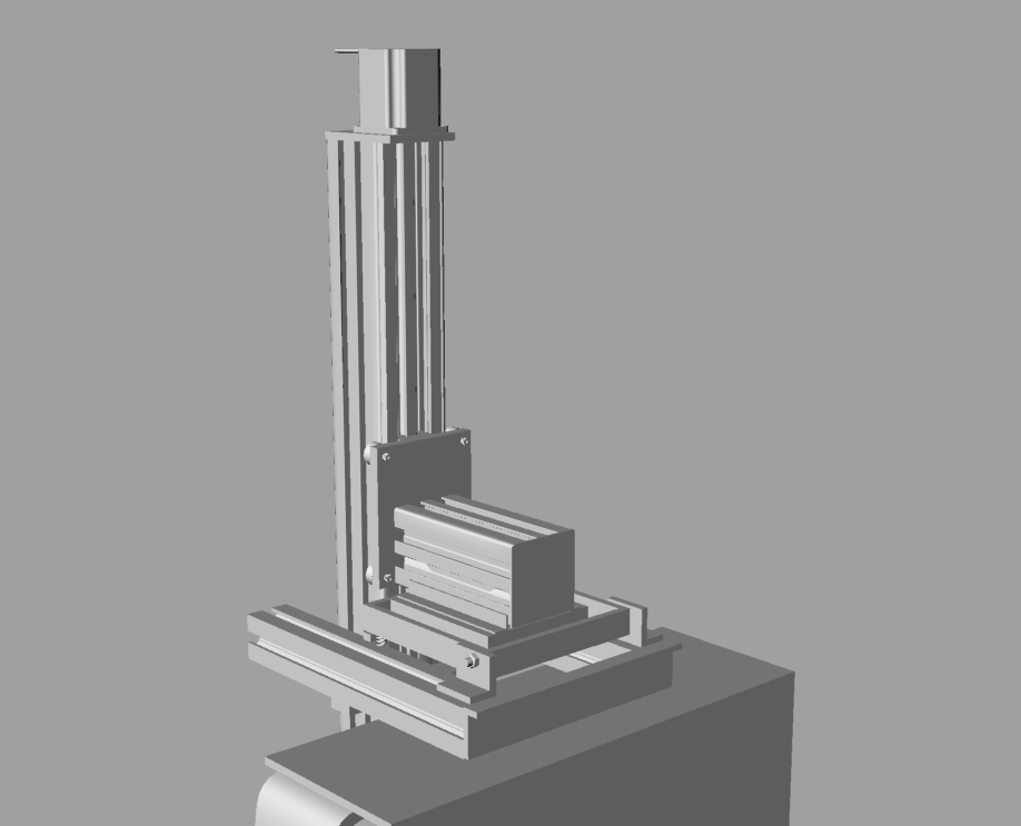
Shown here is a monochrome rendering of the SNYGRO that transitioned into the CS-1. When all the hardware glitches is sorted out we will post a fresh up to date 3D drawing of the CS-1


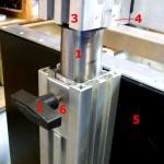
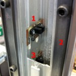
The solenoid cam tilt mechanism.Shown here is just one of the mudular features of the CS-1.The adjustable stainless steel collumn can telescope out to give a 350mm focal depth.The three opto limit switches. I kept these modules all the same for simplicity.It slides inside the main collum and the final calibration is done from the outside with the white abs plastic slide nuts (see fig xx) .1- Square nut. 2- Opto switch.

Shown here is just one of the mudular features of the CS-1.The adjustable stainless steel collumn can telescope out to give a 350mm focal depth.

The three opto limit switches. I kept these modules all the same for simplicity.It slides inside the main collum and the final calibration is done from the outside with the white abs plastic slide nuts (see fig xx) .1- Square nut. 2- Opto switch.

Inside view of the main collumn. 1-Middle Opto slowdow switch(not wired yet) . 2-V-Groove rail. 3-Main collumn.

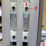
The external adjustable ABS plastic slide nuts for the opto-limit switches. 1-Plastic slide nut. 2-Hex Capscrew


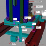
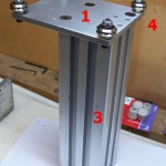
Shown is the horizontal beam (3), bolted to the carriage plate(1).The four small holes are for the leadscrew nut block that slides inside the main collumn

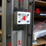
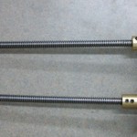
The carbon impregnated nylon anti baclash nut(5) inside the nut block(4) wich will be bolted to the the carriage plate. The Main collumn(1). Acme thread leadscrew.3/8" x 12 (3)

For now I made adapters for the leadscrews,But I am working with a company in china to get steppers with300mm leadscrew shafts.We want to eliminate any backlash possible.


While I am on the Anti- backlash nut,  here are the specs for the acme nut thread:

I used a Carbon impregnated nylon and a Tandem (3/8-12)  tap from :  Link:  Mc Master car

ACME TANDEM from Mc master carr 3/8-12 (12 turns per inch). Thus 25.4mm/12=2.116mm per turn. thus 2.116/200 steps = 0.010 mm per step(wich is 10 microns for each full step.

Diameter 3/8″
Thread Size 12
Type Acme Tap
Helix Angle 29[DEG]
2lbs of force for every ounce of torque  (for plastic nuts)
1.8° Motor 200 steps per revolution x 12 turns per inch (3/8″-12 rods) = 2400 full step or 4800 1/2 step
be prepared to open your wallet(wide) for the TAP (..in 2010 the Tandem tap cost  $80.00(us) from mc master carr)
It is honestly a lot of work to make a anti backlash nut. ….Link:  Hayden Kerk sell them for around $ 50  and is truly there moneys worth.

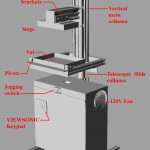
The ChemShapes model1 (CS-1) ,with latest revisions as of AUG 13,2011

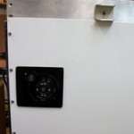
Outside view of keypad

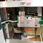
Inside populated and Viewsonic keypad installed